Creating and using new Symbols in Symbol Library
Task details how to create new symbols in Electrical discipline, integrate them into the symbol library and import.
-
Select
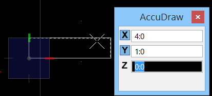
 (Place
Block) and create a Block with a width of 1:0 length of 4:0. Use
AccuDraw for exact dimensions.
Make sure to select the level "Default" when
creating the Block and set the options for color, linetype and linewidth all to
"Bylevel" .
(Place
Block) and create a Block with a width of 1:0 length of 4:0. Use
AccuDraw for exact dimensions.
Make sure to select the level "Default" when
creating the Block and set the options for color, linetype and linewidth all to
"Bylevel" .
-
Next, access the
 (Cell
Library) dialog.
The Cell Library dialog opens.
(Cell
Library) dialog.
The Cell Library dialog opens.
- In Cell Library dialog, select . The Create Cell Library dialog opens.
- Enter a name for the library in File name field, and click Save. The library for Electrical Symbol gets created.
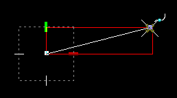
- Next, create a SmartLne from the lower left to the upper right corner of the Block. This construction line is used to define the Cell insertion point.
-
Next, select
 (Define
Cell Origin) to create the Cell origin.
Define Cell insertion point in the middle of
the construction line, again using Snap mode (Center Snap).
Cell Origin point defined.
(Define
Cell Origin) to create the Cell origin.
Define Cell insertion point in the middle of
the construction line, again using Snap mode (Center Snap).
Cell Origin point defined.
-
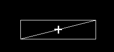
Select construction line with Power Selector and delete it, since
it should not be part of the new Cell.
Next, while the block is selected, click the
 (Create)
tool icon in the toolbar on Cell Library dialog. The
Create Cell dialog opens. Enter the Cell
Name, description and set the cell type to create the cell in the library.
(Create)
tool icon in the toolbar on Cell Library dialog. The
Create Cell dialog opens. Enter the Cell
Name, description and set the cell type to create the cell in the library.
The Cell Name will appear in the list in Cell Library dialog.
- Double click on the Cell name (or ) to place the active cell in the drawing.
-
Now, select
 (Symbol
Manager).
The
Symbol Manager dialog opens.
(Symbol
Manager).
The
Symbol Manager dialog opens.
- In the treeview on the left pane, select the group TUBES CLOSED.
- In the symbols list on the right, scroll down to the last symbol entry.
- Click New to create new symbol record, next in the symbol list.
A new entry is created and a red 'X' is displayed as a placeholder for the new symbol.
-
Keep the Symbol tab activated, and click
 to select the
cell (symbol) in the drawing.
Focus shifts in the drawing view. Select the
cell you inserted in the previous steps.
to select the
cell (symbol) in the drawing.
Focus shifts in the drawing view. Select the
cell you inserted in the previous steps.
-
Enter the 2D Cell Name, Description and click
Save.
The new symbol gets added to the symbol
library.
The newly added cell symbol icon replaces the red 'X' in record in the symbols list view.